Problem: Multi-stage, Multi-controller Algorithm
I was required to implement a control algorithm which automatically adjusts the temperatures of some circulating fluids with very high precision. The specifications of the algorithm were as follows:
- Negative feedback with multiple PID controllers is utilized.
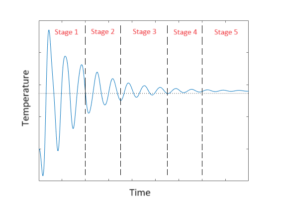
- Since very high precision is required, the overall control process is separated into multiple stages. The early stages provide coarse adjustments of the target temperatures while the late stages provide fine adjustments.
- Each stage employs a control strategy. For example, one stage employs cascade control, with the output of one controller adjusting the set-point of the second controller. Different stages can adopt different strategies, or the same strategy but different parameters.
- Each controller measures the temperature of a specific location of the system as its feedback signal, and compute the output signal at its own cycle period.
- The control will automatically advance the current stage to the next if and only if all the criteria of the next stage are met. But conversely, if any one of the criteria of the current stage is no longer met, then the control will revert to its previous stage. (These criteria include that both the absolute values and the rates of change of some temperatures need to lie within certain ranges as well as for certain durations.)
System Element 1: State Machine
It is natural to model our stages and their relationship altogether as a state machine. A state machine in code helps systematically allocate the correct conditions for stage advancement and reversion to each stage. The big picture of our algorithm can then be summarized by the diagram below.
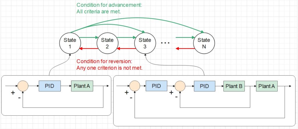
State machine with each state corresponding to a unique control strategy, single feedback control or cascade control as shown for example.
Our state machine will transition its state according to the pre-defined conditions, namely whether the absolute temperatures, the rates of change of temperatures, and the durations have met the requirements. Stored in the memory of the state machine are not only the control stage (i.e. the state), but also the past data needed to determine if the criteria are met (e.g. temperature in the past is needed to calculate the rate of change). These internal variables are updated by pre-defined state-transition actions. (E.g. During a state transition, the durations are reset as zero so that timing can restart for the new stage).
System Element 2: Multi-threading
Since certain stages involve multiple control loops operating simultaneously at different cyclic periods, it makes sense to implement each control loop in an independent thread. In the cascade control depicted below, two threads are run continuously. The first thread measures the feedback signal from Plant A, uses it to compute the output of PID Controller 1, and repeats these procedures at every Period 1. Then the second thread collects both the output of Controller 1 and the feedback from Plant B, computes the output of Controller 2, and similarly repeats its procedures at every Period 2. The second thread accesses the result computed by the first thread through their shared memory.

Integrate the Elements
Now that we have decided on a state machine to help transition the stages, and multi-threading to allow distinct controllers to operate in their own independent periods, how should we integrate these two elements together?
To achieve this, it is important to realize that the two elements break down the overall algorithmic problem from different perspectives. The state machine breaks it down into a series of stages, while the multi-threading breaks it down into independent controllers.
This means we have two options for the integration:
- Let the state machine dominate the logic of the entire algorithm, and each state chooses which set of controllers (i.e. threads) to run.
- Let all threads run continuously and dominate the algorithm. At each cycle, each thread updates the state by calling the API of the state machine. In turns, each thread performs the specific operations corresponding to the new state.
One vital consideration in software design is to minimize the system complexity, so as to ensure high maintainability. Considering that the number of distinct control loops is fewer than the number of states, and modifications to the control loop designs occur less frequently than those to the state transition designs, it was preferable to allow the threads to call the state machine, rather than having the state machine manage the threads. This choice of relationship leads to the program flow shown in the sequence diagram below.
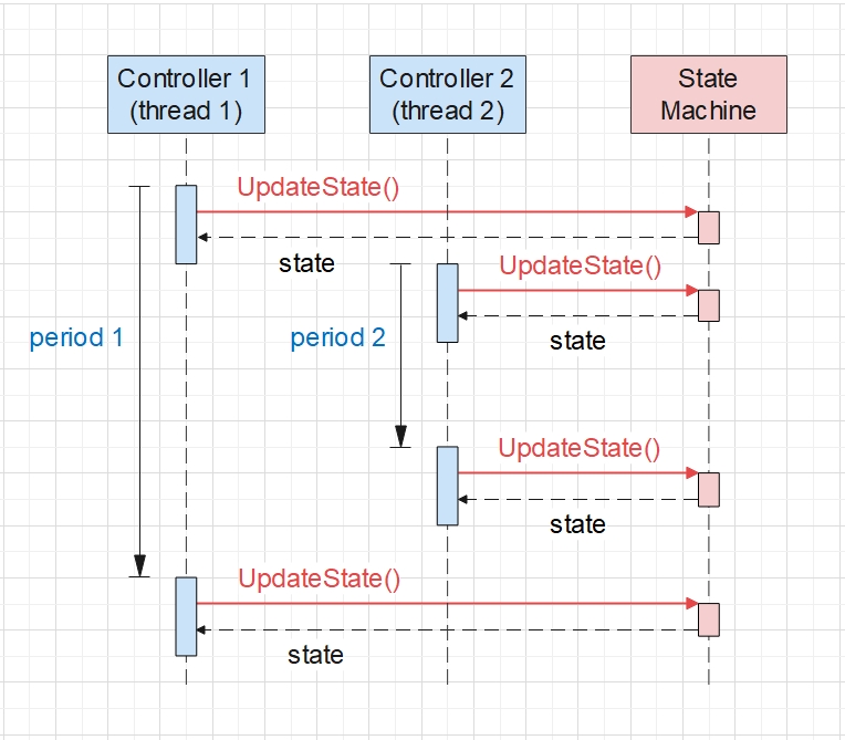
With the aid of thread locks, we can make sure that the state machine is called by only one thread at any given time, avoiding any data race. The thread locks also ensure that in the case of cascade control loops, all necessary computations in the first thread have completed before the next thread retrieves the result from the shared memory.
Finally, in order to switch between the single-loop control and cascade control, the state is returned to each thread so that each thread can pause its operation when the current state doesn’t require the corresponding control loop.
Conclusion
Designing the software implementation of this algorithm gave me the opportunity to take a comprehensive look into the synergy between a state machine and multi-threading. While a state machine can automatically check for conditions and invoke internal state-transition actions, external threads can obtain the newest state at any time and adjust the interactions between themselves accordingly. Together they solve problems involving simultaneous tasks influenced by the same set of criteria.
