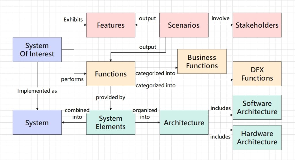
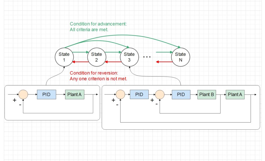
In this post I aim to present my design of an industrial data management system that orchestrates the interactions between various data-driven applications. The design will showcase how diverse technologies integrate to create a cohesive system.
Understand the Needs – Data as the Core Driving Force
Imagine the following scenarios which our system needs to accommodate:
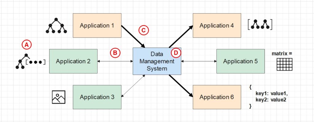
- Each application relies on a unique set of data to run, so developers should define a custom data structure for each application in order to keep the data organized. All data structures should be managed by our system.
- Data of an application can be modified manually or automatically by the application itself.
- Multiple applications operate cohesively to accomplish specific business objectives. Modifying the data in one application should immediately change how some other dependent applications run.
- End-users want to read and modify data of all applications through a single graphical user interface (GUI).
Shown below is the visualization of these scenarios. Different applications are driven by different structured data (e.g. tree with embedded arrays, array of complex structures, images, hash-maps, etc). The bold arrows imply that data modification in Application 1 will affect Application 4 and 6. Our central data management system acts as a coordinator for all applications, with its main functions A, B, C and D to be described next.
Role of Our System – A Coordinator
To satisfy these scenarios, our management system needs to perform the following functions:
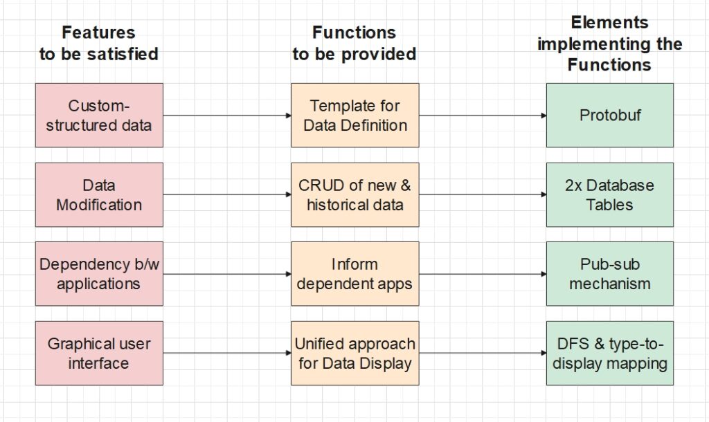
- Provide a standard template for developers to define custom data structures, so that the system can manage different types of data with a unified approach.
- Support CRUD operations as well as storage of historical data.
- Record the data dependency between applications, and inform all the dependent applications immediately after the depended application has modified its data.
- Provide a unified approach to display the distinctly-structured data on the GUI, so as to avoid extra adaptation when new structures are defined.
Note that all these functions rely on a suitable communication network which enables continuous data transfer between the management system and all the applications.
Design System Elements
Each function requires making a choice among available technologies. Here instead of diving deeply into the choices available, I will only showcase how each of my choices suits our needs. In this way we will see the final architecture very soon.
A. Protocol Buffer as the underlying data format
To implement our system, we first need to define the data format which everything else relies on. Our choice is Protocol Buffer (a.k.a. protobuf).
Protobuf is a data format developed by Google to be smaller and faster than XML and JSON. It achieves this by serializing the data before passing it to the communication network.
In our use-case, users can define their own data structures using the .proto file syntax (example shown below). Then from these definitions, we generate corresponding source codes in the programming language of our application (e.g. C++, Python, etc). These source codes provide convenient methods to manipulate the data, including transforming the data into human-readable JSON format.
// polyline.proto
syntax = "proto3";
message Point {
  required int32 x = 1;
  required int32 y = 2;
  optional string label = 3;
}
message Polyline {
  repeated Point points = 1 [(array_size)=2];
  optional string label = 2;
}
(A note on accommodating image data)
Images or other complex data can be stored in a Protobuf field of bytes type, which can contain any arbitrary sequence of raw bytes.
message Image {
    required bytes data = 1;
}
B. Store structured data as binaries in Database
Protobuf data are manipulated in binary format both within the applications and along the communication pipeline. Therefore it makes sense to store the data in binary format too to avoid unnecessary re-formatting.
Two tables in a relational database can be used to store the up-to-date data and the historical data separately. The two tables can possess the same columns to facilitate data transfer between them – every time when data of an application need to update, the row with the old data can be transferred from the up-to-date table to the historical table, and then a new row with the new data can be inserted into the up-to-date table. In this way the up-to-date table holds only the newest version of data for each application, making the query very simple.
| name | binary_data | creation_timestamp | version |
|---|---|---|---|
| Application 1 | (? bytes) | YYYY-MM-DD hh:mm:ss | 18 |
| … | … | … | … |
| Application 6 | (? bytes) | YYYY-MM-DD hh:mm:ss | 26 |
C. Publisher-subscriber pattern to trigger responses
One important scenario in our business is to trigger responses from applications every time a certain application has its data modified. We achieve this through the Publisher-Subscriber (Pub-Sub) architectural design pattern.
Normally, Pub-Sub lets the depended application to be the publisher, which sends a message (our new data) to different queues for each subscriber to consume. But in our business requirement, we also want the new data to be permanently stored in our data management system, which contains our database. So we decided to let the management system to be the real publisher instead. The entire sequence of actions is as follows.
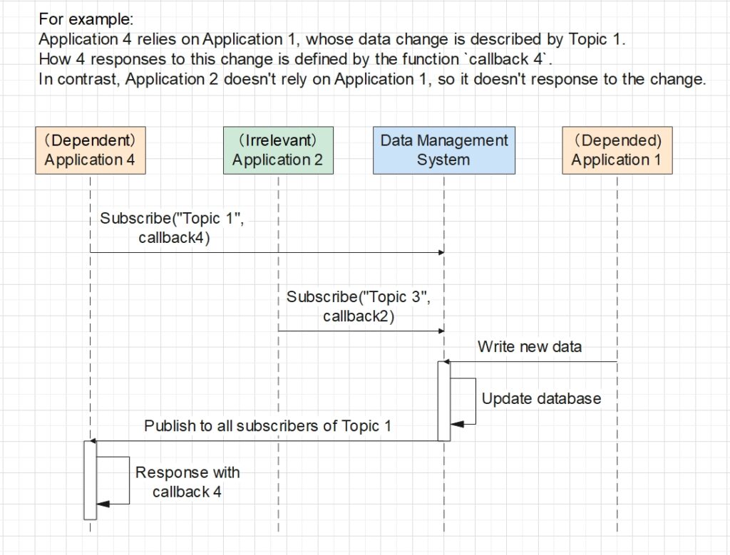
- Before any business runs, the dependent Application 4 subscribes to a topic specific to the data modification event of the depended Application 1, i.e. Topic 1. A topic is an identifier allowing the system to manage different dependency relationships separately.
- When the business is running, Application 1 sends the new data to the management system.
- The management system updates the data in the database.
- The system identifies the topic corresponding to the data received, i.e. Topic 1, and publish a request to every application which has subscribed to this topic.
- After having received the request, Application 4 executes its predefined callback function as a response to the data change of Application 1.
D. Unified Display Algorithm for a variety of data structures
Recall that each application defines their own data structures, and the end-users want to visually examine data of all applications through a GUI. In order to ensure the scalability of the GUI, we need a unified approach to display all these distinct structures.
Let’s go back to our .proto definition example. It can be easily noticed that we defined a tree. Its root is an object of type Polyline which contains two children – an array with elements of type Point and a string. This has inspired us to define each data structure as a tree, with its nodes being any arbitrary type suiting the business needs. In other words, we enforce any data to be defined under a tree root.
Then, in order to automate the display, we can pre-define a DFS algorithm and a logic to map each data type to a chosen display mode. When DFS is run on the Polyline tree, the mapping logic identifies its child node points to be of type repeated Point, i.e. an array, and automatically applies the predefined display mode for array to points. Similarly, as DFS continues to traverse and reaches the x, y and label members inside each array element, the mapping logic applies the corresponding display modes for type int32 and string to the members.
Shown below is the visualization of the tree example in XML format. DFS reveals the entire tree structure, and the mapping logic will display each tree node on the GUI according to its data type.
<root type="Polyline">
    <points type="Point" repeated="true" index="0">
        <x type="int32">0</x>
        <y type="int32">0</y>
        <label type="string">source</label>
    </points>
    <points type="Point" repeated="true" index="1">
        <x type="int32">5</x>
        <y type="int32">20</y>
        <label type="string">destination</label>
    </points>
    <label type="string">path</label>
</root>
(A note on automatically displaying image data)
To automatically display the complex data stored in the Protobuf bytes field, a custom identifier known as “field option” can be defined and added to the field to help identify whether we want to display the data as an image, an audio, or any other format.
message Image {
    required bytes data = 1 [(display)=IMAGE];    // IMAGE is a enum value.
}
How have Our Elements worked together?
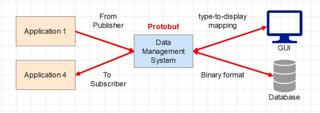
Putting all the system elements together gives the overall design shown in the diagram above. The business applications can now interact with each other through the pub-sub mechanism managed by our system. Behind the scene, all data are defined in the Protobuf format, so as to facilitate data transfer in the communication network. Taking advantage of the fact that Protobuf handles all data in binary format, we chose to store the data in binary format too in our database, for the sake of simplicity. Finally, with the aid of predefined display modes for each data type, we can display any custom data structures on the end-user GUI without having to worry about adapting to new structures in the future.
This wraps up the case study of my bespoke data management system. We started off with understanding the needs, then we pinpointed what functions our system needs to perform. From that point onward, we took some effort in designing each system element to implement each function. At the end we put the elements together and let them work cohesively. Along the process I had applied the system design methodology I described in my previous post. I hope you have enjoyed this case-study, and please let me know your thoughts in the comment section below!
